发布者: Guangdong Aucas Network Technology Co Ltd /  2021-09-22 /
  3362 /

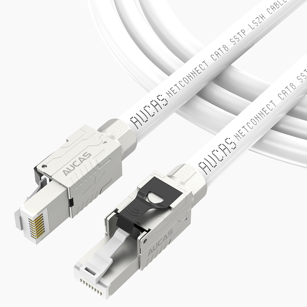
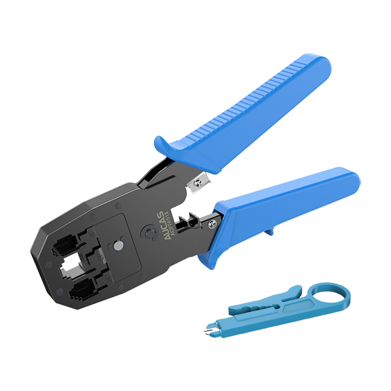
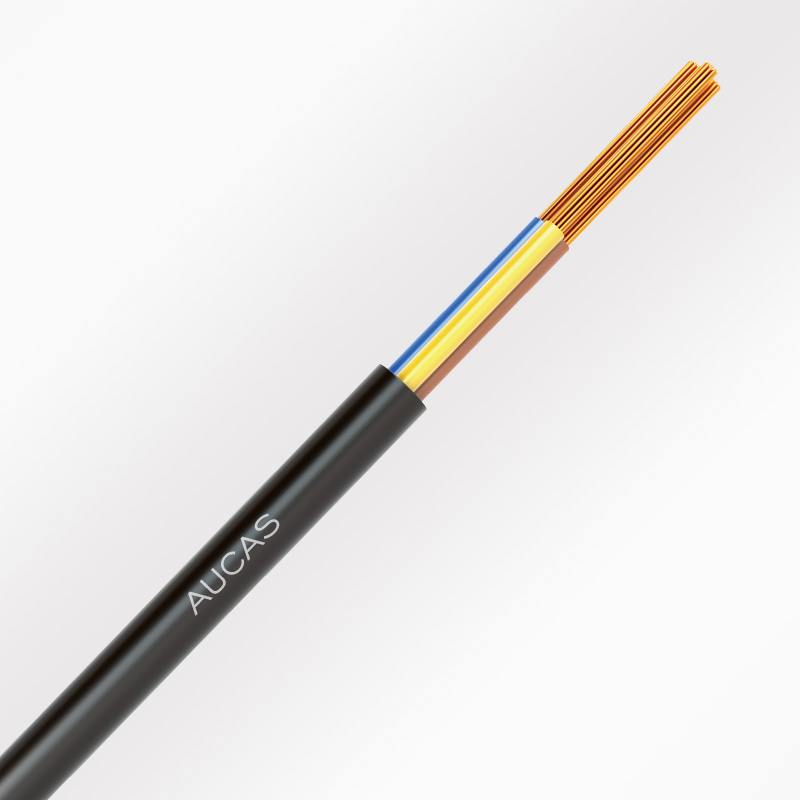
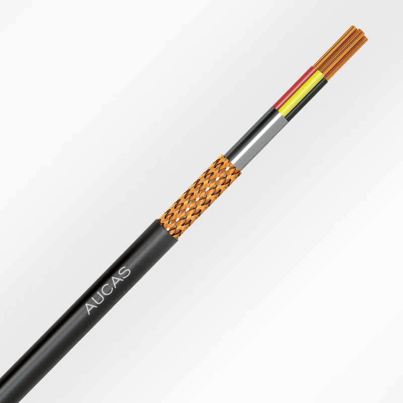
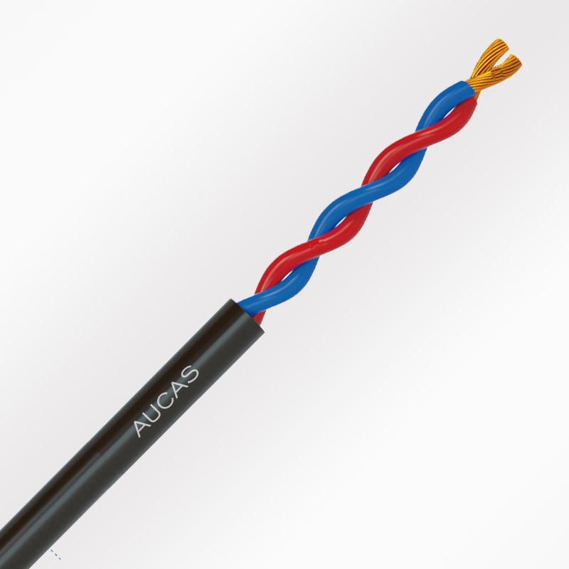
What are the construction steps of network cabling project? Cabling is a modular, highly flexible information transmission channel within a building or between groups of buildings. It enables voice, data, image devices and switching devices to be connected to other information management systems and to be connected to the outside world. It also includes all cables and associated connecting parts between the connection points of the external network or telecommunication lines of the building and the equipment of the application system. The integrated cabling system consists of different series and specifications of components, including: transmission media, related connection hardware (such as distribution frames, connectors, sockets, plugs, adapters) and electrical protection equipment. These components can be used to build various subsystems, each of which has its own specific purpose.
The integrated wiring system is divided into seven parts: work area; Wiring subsystem; Trunk subsystem; Architectural subsystem; Equipment room; Interline and management. In fact, certain laws should be followed in the wiring work, which is not only reflected in the relevant norms and standards to be followed in the implementation of structured wiring engineering.

Preparation before construction of integrated cabling
As a construction organizer, we must have a clear mind and a sense of responsibility. According to the completion time of the pipe groove and the time requirements of the subsequent wiring system installation and decoration, the wiring schedule and quality assurance measures are listed. Before routing cables, strictly check them. For details, see the corresponding pipe groove check requirements. The quality problems that seriously affect the routing quality and progress are as follows: The size of the pipe groove is small; There are burrs at the junction; Buried installation pipe slot obstruction, water, etc.; Before routing a buried pipe trough, try it on thoroughly. Documents to be obtained include: cabling system diagram; Layout of wiring system; Threading technical requirements and blank threading report.
Implementation of integrated wiring project
The key to organizing the threading is the construction organizer, the construction organizer should: understand the overall structure of the wiring system, do not wear the wrong route; Can clearly distinguish the various cables to be laid, do not use the wrong cable; Familiar with the cable to pass through the pipeline, have rich experience in threading; Know how to prevent typical problems that affect threading quality and schedule; Understand the special requirements of cable laying in integrated cabling systems; Clear thinking, grouping the information points, laying them one group at a time, not wearing much, not leaking through; Each group should not exceed 20 information points, otherwise at the same time, the amount of cable through and release is large, laborious and easy to lead to cable damage, but also easy to wind, knot, very affect the progress; Strictly do the label, and record the length scale; Strictly organize the test, and use the detection instrument to check the status of each cable.
Threading shall be carried out in accordance with process requirements. Pipe groove inspection, steel pipe protection, buried steel pipe fitting. Explain the wiring system structure, wiring process, quality points and pay attention to cable protection to all personnel involved in wiring. Plan groups, thread cables one by one, for one group, select the starting point. Cable to the starting point, label, mark the end of the distribution frame, thread this group to the distribution frame, leave the remaining length as required. Measure length from starting point to socket end, truncation, label, mark socket end scale. The socket end is coiled inside the socket box. Perform on-off test for each cable, re-thread, and correct label errors. Finally, arrange the threading report and fasten the cable trough cover.
The remaining length (length + width + depth) calculated from the entrance of the distribution cabinet at the distribution box is that of the distribution cabinet. Cabinets and cable troughs should be in good order. The remaining cables should be grouped according to the grouping table and bundled from the outlet of the cable trough with a binding point spacing of no more than 50cm. Do not bind cables with wire or hard power cables. The bend radius of a 50-core cable should be at least 162mm. When a vertical cable is routed from a cable box to a vertical steel pipe at the lower layer, bind the suspension in the cable box to prevent the weight of the cable from leaning on the inner cable at the Angle. This may affect the transmission characteristics of the cable. The cables laid in the troughs should be straight, without winding, and of different lengths.
Cables are labeled according to the design plan, each label corresponds to a 4-pair cable, and the corresponding room and socket position cannot be mistaken. The labels at both ends are 25 cm away from the end. Attach light-colored plastic tape, write labels with an oil-based pen or attach paper labels, and then wrap transparent tape. In addition, at the end of the distribution frame from the end to the entrance of the distribution cabinet every 1 meters, attach the label paper to the outer cover of the cable and write the label with an oil pen. Route four pairs of twisted-pair cables at a ratio of 3% through the spare cables. Place the spare cables in the trunk slot. Each layer has at least one spare cable.
After the wiring is complete, all 4 pairs of core cables should be fully tested. Test method: Peel off the core wires of both ends of the cable to expose the copper core. Switch the digital multimeter to the on-off test gear at one end, and the two pens are stably connected to a pair of cable cores; Touch the pair of cable cores briefly at the other end. If the holder can hear intermittent sounds, it is OK. Test the four pairs of cores of each cable. The problems that this test can find are broken wires, short circuits, and labeling errors.
Guarantee measures for construction quality of network cabling project
1, to do a good job in the design phase of the detailed drawings, drawings are very important. Do not think that it is very simple, a good integrated wiring design drawing can save your wiring time and some on-site problems encountered in the wiring process, because the building is not only weak electricity, but also strong electricity, fire, air conditioning and so on.
2, in the construction process to do a good job of construction plans to cope with constant changes. Because sometimes plans don't change.
3, to timely understand the progress of other parts of the entire project, in order to adjust the construction plan in time.
4, strict construction. The line should be neat and clear.
5, to do the label, or to the back of the trouble.
The above is the relevant introduction of the construction of network wiring engineering for your reference.
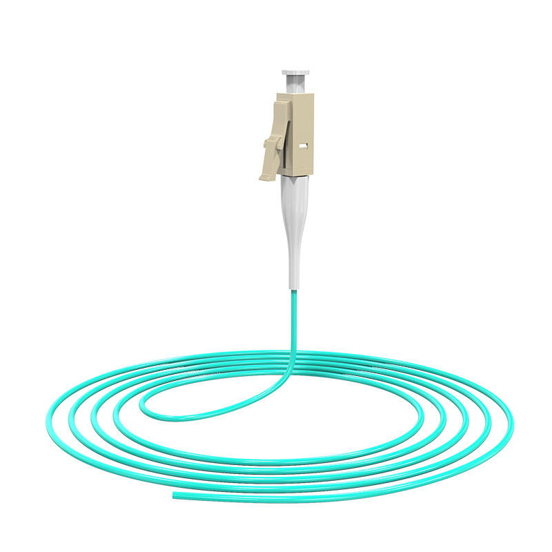
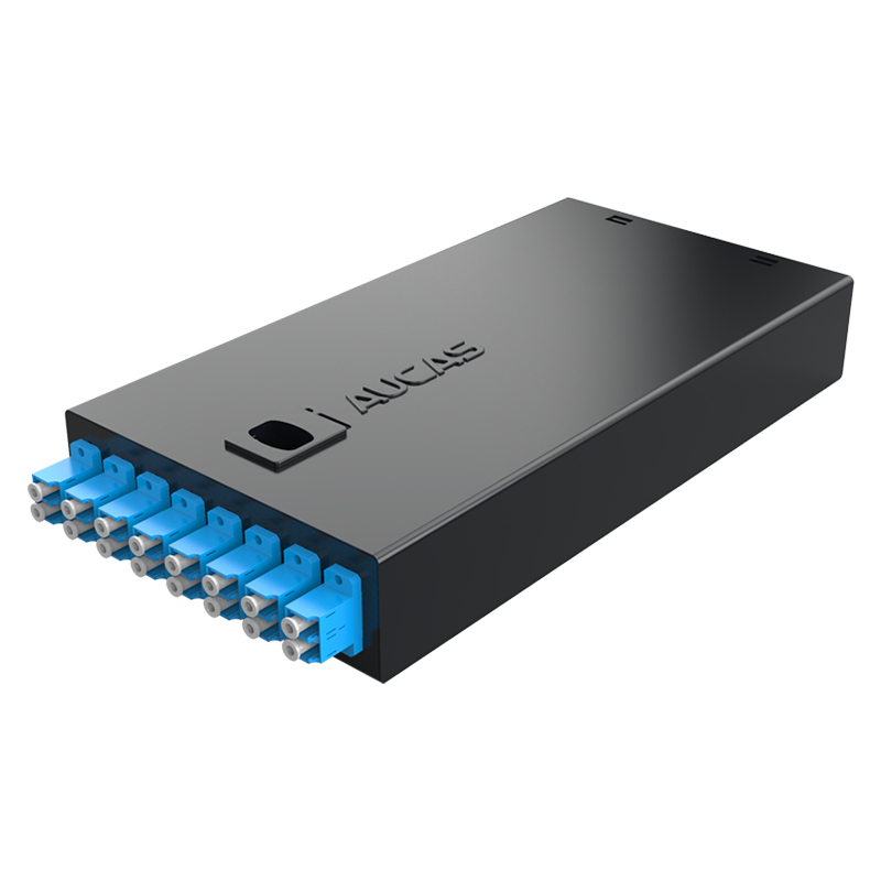
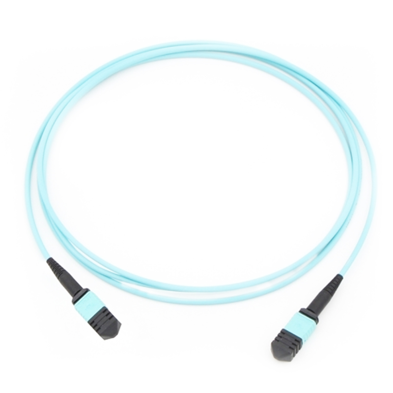
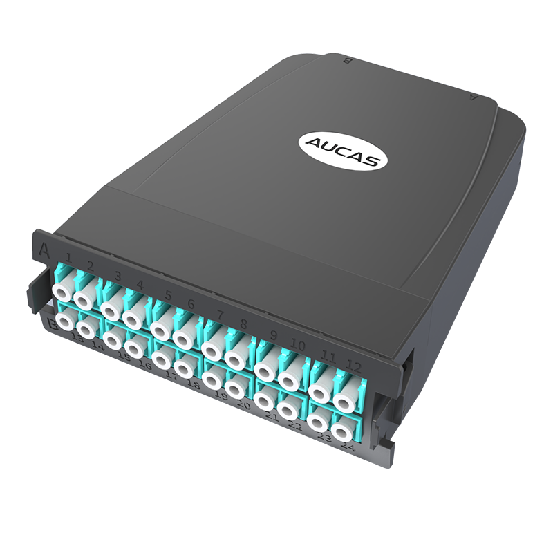
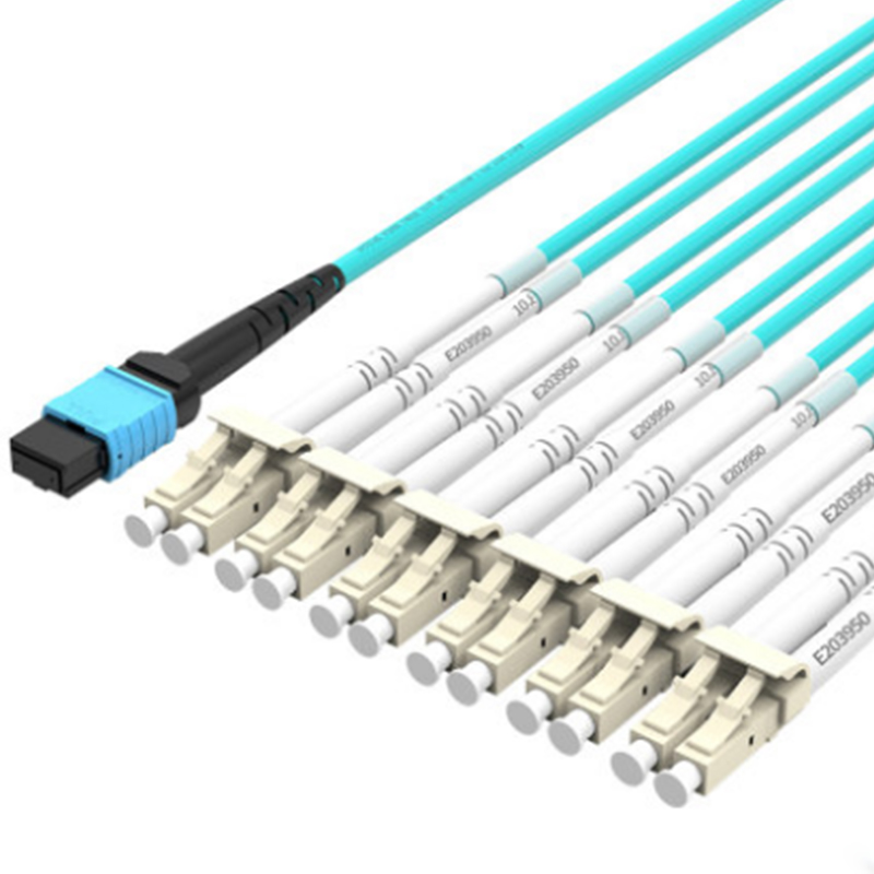
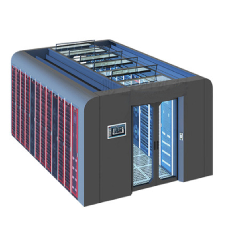
Aucas Technology is a high-tech enterprise integrating the independent development, design, production and sales of copper cable wiring, optical cable wiring, intelligent electronic wiring frame solution, data center MTP/MPO high-density solution, data center cold channel solution, eight kinds of copper cable solutions, security cable and intelligent management wiring system platform. The company is oriented to the pursuit of user needs, and provides customers with attractive products of Aucas. Aucas cabling provide four colors convenient!


 下载中心
下载中心


 大客户中心
大客户中心